You’ve got questions
we’ve got answers.
Answer : Connect the 12V DC power adapter into the 12V DC power jack on the back of the UCM62XX.

Connect LAN cable into WAN port it will display ip address from dhcp server. Once the UCM6204 is successfully connected to network, the LCD will display the IP address.
You can also connect through the LAN port (default ip 192.168.2.1)
.
Answer : Type UCM ip address in the web browser address bar, for example, if the LCD shows 192.168.1.118, and 192.168.1.118 is entered into the web browser.
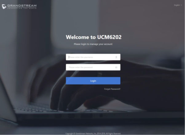
Enter default administrator username “admin” and password. A unique random password printed on the sticker located on the back of the unit.
After logging into the UCM web portal for the first time, the setup wizard will guide the user through basic configurations such as time zone, network settings, trunks, and routing rules.

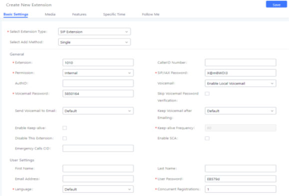
Answer : To manually create new SIP user, go to Web GUIExtension/TrunkExtensions. Click on "Add" and a new dialog window will show for users to fill in the extension information.
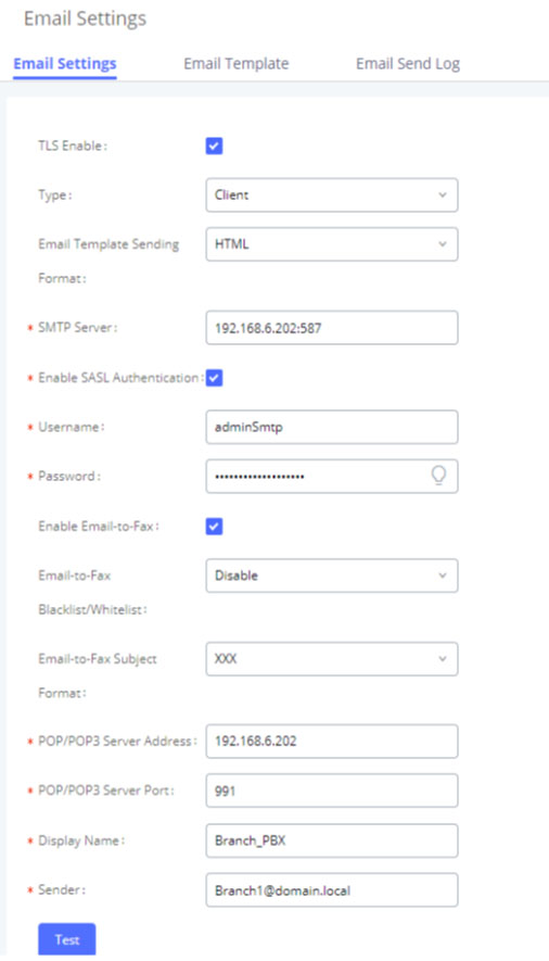
Answer : You need to setup an email account on the UCM62xx and whenever you’re not able to logged in web ui press the forgot password option & UCm62xx will send the existing password to your mail id from the setup email account.
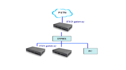
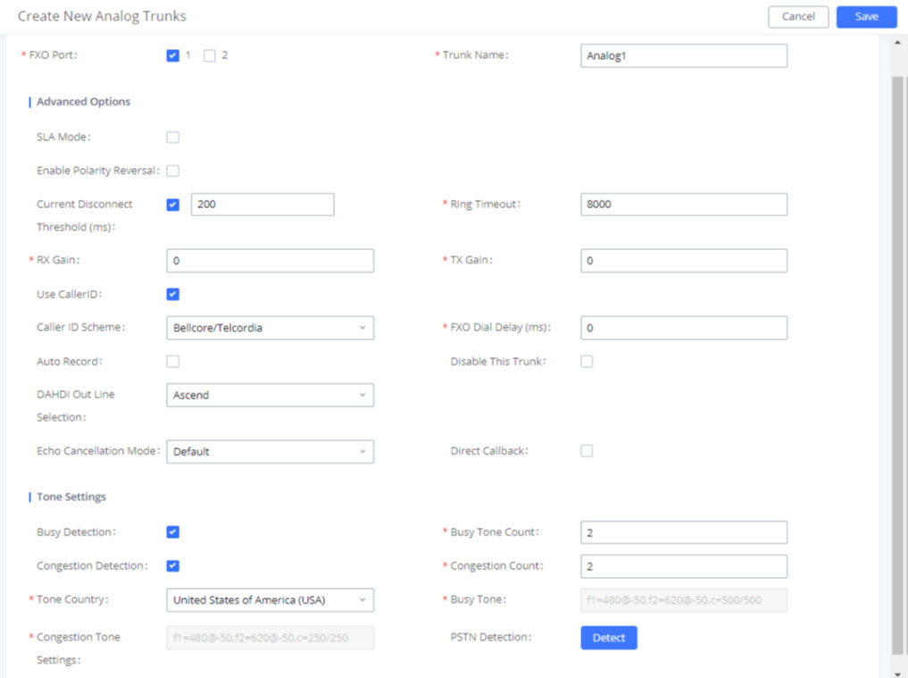
Answer : The UCM6200 series has built in FXO ports which allows it to pull in PSTN lines and provide analog trunk service.
Answer : Auto-Discovery of Sip Endpoints.
Auto-Provision of Grandstream Sip Endpoints.
Zero config can be manged by remotely.

Note:- It is recommended to upgrade UCM to latest firmware for product lifespan and security improvements.
For the further support please feel free to write us on techsupport@cloudinfotech.co.in & our team will be get back to you.
Answer : The GVC3200 have 2 Mega pixel camera with 12X optical zoom support.
Answer : Yes, the GVC3200 supports up to 9 way video conferencing.
- - 4 way supports 1080p resolution
- - 5 way supports 720p resolution
- - 9 way supports VGA resolution.
Answer : DND can be enabled by pressing Mute button from the remote control, or clicking on DND from Web UI (on the upper right).To). To disable DND, simply press the Mute button again.
Answer : No, the GVC3200 currently does not support PoE power supply.
Answer : Yes, While on a conference call, users can click on * button from remote control to manually start or end the recording. And, user can store the recording file in the USB device or can manage the file remotely via GVC3200 Web UI > Maintenance > Recording.
Answer : Yes, the GVC3200 supports Grandstream’s robust IPVideoTalk platform for plug and play video conferencing while also being interoperable with any 3rd party SIP video conferencing platform - thus offering a great option to expand or implement a 3rd party platform.
Answer : The GVC3200 Allows Android 4.4.2 compliant applications to be deployed in the device with provisioning control.
Answer : Yes, When GVC3200 is powered up, use a small pin to press the reset button one time to reboot and When powering up GVC3200, keep pressing the button with a small pin for more than 10 seconds to restore to factory settings.
Answer :
Yes, the GVC 3200 supports screen lock security.
To use this feature -
- o On GVC3200 LCD menu→Settings→System→Security, select Screen Lock and set Screen Lock code.
- o Reboot, enter sleep mode or power off the GVC3200.
- o When the GVC3200 boots up again, a screen lock code will be required. The user can unlock the screen by entering the code using the GVC remote control.
Answer : Yes, the GVC3200 have integrated dual-Band WiFi supprt. On the LCD display, go to Settings→Network→Wi-Fi to turn on and configure Wi-Fi.
Answer : The GVC3200 supports Up to 1080p, 30fps for frame rate and 4096Kbps for video bit rate.
Answer : The GVC3200 support 4 different accounts:
- • SIP account: Can be registered with any SIP Server/IPPBX, or use IP calls with another SIP end device.
- • H.323 account: Can be registered with any H.323 Platform, or use IP calls with another H.323 end device.
- • IPVideoTalk account: Can be registered with IPVideoTalk cloud service, please refer to www.ipvideotalk.com.
- • BlueJeans account: Can be used to join Bluejeans meetings without the necessity of installing Bluejeans application.
Answer : Yes, the GVC3200 supports manual backup and automatic backup of data. It can be accessed from Home screen→Applications→Backup.
- • Press the red shortcut key on the remote control to create new backup manually. The user will select data and press the blue shortcut key to start backup.
- • Press the yellow shortcut key on the remote control to access automatic backup. Then configure each parameter for automatic backup.
Answer :
Video: H264 (Baseline, Main, and High Profiles).
Audio: G.711μ/a, G.722 (wide-band), Opus, G.722.1, G.722.1c.
Please note Opus is supported on SIP and Bluejeans accounts only.
Answer : No, upgrading the Android version on the GVC3200 is not supported.
Answer : We can connect cellphones with Bluetooth, GAC2500 or any other Bluetooth speaker model with the GVC3200 via Bluetooth.
Answer : Yes, in order to connect GVC3200 with GAC2500 via USB cable, please make sure the GVC3200 firmware version is equal to or higher than 1.0.1.30
Answer : Default IP is 192.168.11.1
Answer : Device have a reset button of back side so we can press this button for 15 seconds after that hard reboot (Restart) this device.
Answer :First, We need to connect analog phone to any FXS port and check dial tone is coming or not if coming than dial *158# and try to listen the IP of this device.
Answer : 1) First open the device on web through the default IP.
2) Click on Quick configuration and change the default IP.
3) Now add the server IP with port number.
4) Now we can select only one port or a batch as per our requirement.
5) Fill the required SIP extension details like:- User name, Ext. No,
Password etc.
6) Now click on next and reboot (Restart) the device after reboot device is
Ready to use with SIP server.
Answer :Assuming the IP address of a device is 192.168.1 200 , subnet mask is 255.255. 255 .0, IP of gateway is 192.168.1.1 , configured as follows:
- 1) Connect a telephone to FXS port.
- 2) Pickup the telephone , Dial *150*1# . Hang up after hearing "setting successful"
- 3) Pickup the telephone Dial *152*192*168 *1*200 #" . Hang-up after hearing "set success"
- 4) Pick up the telephone . Dial *153*255*255*255*0# .Hang up after hearing "setting successful"
- 5) Pick up the telephone . Dial *156*192*168 *1*1# . Hang up after hearing" setting successful"
- 6) Pick up the telephone . Dial *158 #. It will play IVR about the IP of the device.
Answer :
Assuming the IP address of a device is 192.168.1 200 , subnet mask is 255.255.255.0, IP of gateway is 192.168.1.1, configured as follows:
1) Connect a PSTN line to FXO port
2) Make a call to the PSTN line . Dial "*150*1# "after hearing "please dial extension number ". Hang up after hearing "setting successful"
3) Make a call to the PSTN line . Dial" *152*192*168*1*200#" after hearing "please dial extension number ". Hang up after hearing "setting successful"
4) Make a call to the PSTN line . Dial"*153*255*255*255*0#" after hearing "please dial extension number ". Hang up after hearing "setting successful"
5) Make a call to the PSTN line . Dial "*156*192*168*1*1#" after hearing "please dial extension number ". Hang up after hearing "setting successful"
6) Make a call to the PSTN line . Dial "*111#" after hearing "please dial extension number ", that will restart the device.
7) Make a call to the PSTN line . Dial"*158#" after hearing "please dial extension number ". It will play IVR about the IP of the device.
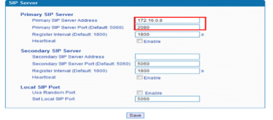
Answer :Click menu "SIP server "
"Primary SIP Server "used for setting the IP and port of Primary SIP server,
Local SIP port set to 5060, default register interval is 1800s, you can
Change it.
Answer :
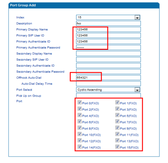
Click menu "Call &Routing"--->" port group "
Fill "Primary Display Name" "Primary SIP User ID ""Primary Authenticate ID”
"Primary Authenticate Password”
Off hook Auto-Dial fill the DID number.
Auto-Dial Delay Time: the delay time to auto dial for incoming call.
Select the port you want to connected as a Trunk.
Answer : Click "Call & Routing ------> IP->Tel Routing "
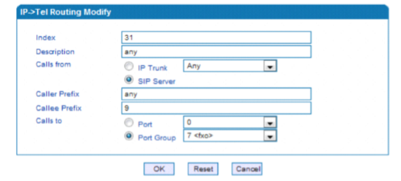
The calls from SIP server which callee prefix is 9will go to FXO port group
Click "Manipulation ---> IP->Tel Callee "
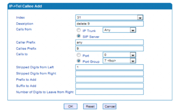
Answer : Click "Call &Routing ------> Tel ->IP Routing "
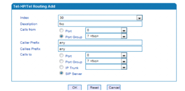
Answer :
Steps to install the GSM Gateway in the network: 1) Connect the power cable with the GSM Gateway
- 2) Connect the network cable at FE0 PORT of the GSM Gateway 3) The default IP of gateway is 192.168.11.1
- 4) After your gateway is in your network then choose one laptop and add the IP of 192.168.11.100 or any 192.168.11.x Series in your laptop so that you can ping the gateway from that laptop.
- 5) Once you got the ping open the gateway in the browser by searching 192.168.11.1.
- 6) Default username and password of the gateway is admin respectively.
- 7) Change the IP Address of the Gateway from the quick setup wizard and give the IP according to the network.
- 8) Restart the gateway
Answer :
Steps to upgrade the firmware:
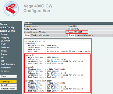
1) Login the web management of the gateway, click “System Information” and check the firmware version.
2) Get the upgrade package from dinstar support
3) Upload the upgrade package. The upgrade package must match 0xxx or 2023xxx. For example,
if the current firmware version is 02230703, the upgrade package must be 02230801.tar.gz,
can’t be 02220801 or 01230801. We should always check the series of the firmware while uploading it.
4) click “Tools” and “Firmware upload”. Select the upgrade package and click “Upload”.
5) After successfully uploading the firmware, restart the gateway.
Answer : Steps to fix BCCH in the GSM Gateway:
1) Change the port’s BCCH mode to default and wait for the available frequencies listed.
2) Change the port’s BCCH mode to fix, and enter the available frequencies. Save.
3) Check the result.
Answer :
Answer: If the GSM antennas are too close, when GSM modules work, the interference appears, and this, of course, affect the performances of Dinstar VoIP GSM Gateway DWG2000 series as bellows:
1. ASR is bad. Before each call, it is communication of SIMs’ data. As there is interference, the communication may fail or the efficiency may be low, then the call will fail or the time of setup a call will be long. Moreover, if GSM Base station is busy, other calls will occupy the station channels as the interference causes the communication efficiency is low on the gateway.
2. SMS/USSD sending is slow. The interference on the data communication will cause re-send or failure
3. Little influence on voice quality. If the call has setup successfully, users won’t feel obviously on the interference. Because the wrong codes on voice is not so serious on voice quality.
So, we recommend
1. Place the antennas at locations where wireless signals are good.
2. As indicated in the picture, the space between antennas should be more than 12cm.
3. Place the antennas in the open areas. Eg Don’t place the antennas close to the big-size metal boxes.
Answer :
Steps to configure GSM Gateway are as follows:
1. Download X-LITE 3.0 and install it.
2. Open X-LITE and click on the small down arrow and then on SIP Account Settings
3. Click on Add
4. In the Account tab, enter your account information
- a. Display name: Your user name.
- b. User name: Your user name.
- c. Password: Your password
- d. Authorization user name: your user name.
- e. Proxy: IP/Domain name of DWG2000 Gateway
- f. Domain Proxy: none
- a. Click Add
- b. IP Address: Laptop/ PC’s Ip address in which your Xlite is installed.
- c. Port: 5060
- d. Description: Any trunk name(eg – Xlite)
- e. Keep Alive: Enable
7. Finish
Answer :
Steps to do call routing the GSM gateway:
1) Click Call configuration
2) For outgoing call, Click IP>Tel
- a) Description: Any (eg. X-lite)
- b) Source: Select the trunk from which you want call to pass
- c) Destination: port group o
or any port from which you want to call to move. - d) Call Restrictions: Allow Call
- a) Description: Any (eg. X-lite)
- b) Source: port group o
or any port from which you want to call to land - c) Destination: Select the respective trunk in which you the call to land
- d) Call Restrictions: Allow Call
4) Finish
Answer :
Steps to send SMS from the Gateway are as follows:
1) Click SMS/USSD option.
2) To send SMS:
- a) Port: Select the port through which SMS messages are sent.
- b) To: The number where the SMS message will be sent.
- c) UCS2: Supports English and Chinese.
- d) GSM 7bit: Supports English only.
- e) Message: The content of message.
Answer :
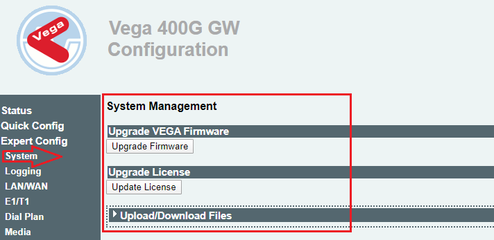
Log into the Web interface and go to "System Setting ->Then you can use this function.
Answer :
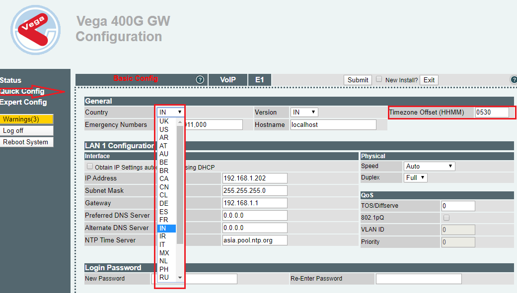
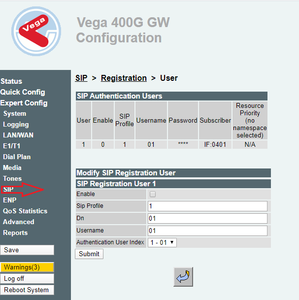
Sangoma vega have 2 LAN, Port 1st port on DHCP & 2nd port default Static IP Address – 192.168.168.2,

Answer :
set lan.if.1.use_dhcp=0
set lan.if.1.ip=192.168.20.48
set lan.if.1.subnet=255.255.255.0
set lan.gateway.ip=192.168.20.254
set lan.gateway.dhcp_if=0
set sip.lan_profile=1
save
reboot system
Answer : A network switch is networking hardware that connects devices on a computer network by using packet switching to receive and forward data to the destination device. It is a L2 and L3 devices also read MAC address.
Answer :
Connect the power cable into AC power socket.
Connect an Ethernet cable into an outgoing port on your modem or router – sometimes marked as a
“WAN” port (on a router – any port will do)
- 1.Take the other end of the Ethernet cable and plug it into any port on your switch
- 2.Now plug another Ethernet cable cable into another port on your switch
- 3.Plug the other end of the Ethernet cable into your device
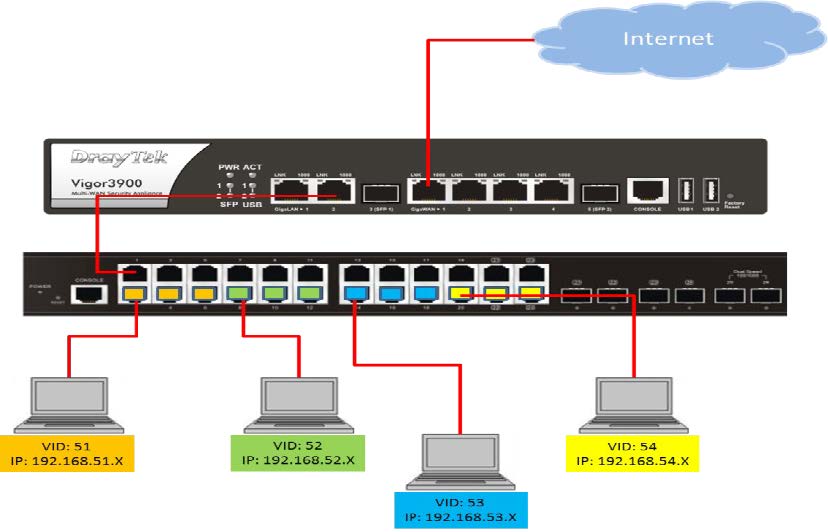
Answer : An Unmanaged Switch allows devices connected to a network (LAN) to communicate with each other. It is a plug-and-play switch.
Answer : “No” Configuration is not allow in this type of switch.
Answer : A managed switch provides the ability to configure, manage, and monitor your Local Area Network (LAN). This provides advanced features to control your LAN traffic. We can modify it according to our requirment.
Answer :
•Spanning Tree Protocol support for switch and link redundancy without creating loops;
•the ability to implement quality of service;
•VLAN support;
•bandwidth rate limiting
Answer : “YES” A managed switch will act like an unmanaged switch essentially. (there is no config on it yet).
Answer :
A layer 2 switch is a type of network switch or device that works on the data link layer (OSI Layer
2) and utilizes MAC Address to determine the path through where the frames are to be forwarded.
Layer 2 switch Can communicate within a network only.
Answer :
A layer-3 switch can perform some or all of the functions normally performed by a router. Layer-3
switches typically support IP routing between VLANs configured on the switch. Some layer-3
switches support the routing protocols.
Layer 3 switch Can communicate within or outside network.
Answer : Layer 3 switch support protocols like STATIC, OSPF, EIGRP, RIP, BGP, MPLS.
Answer : “YES” we can use it as a router. If orgination work on any protcol like OSPF, EIGRP, RIP, BGP etc.
Answer : “NO” layer 3 switch is not support NAT. But some advance series support NAT.
Answer :
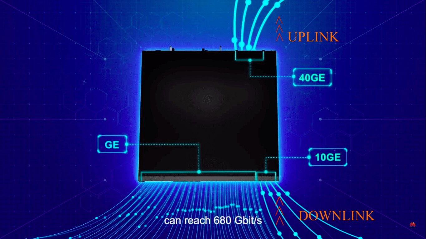
The uplink port on switch is used to connect a device or smaller local network to a larger network.
The downlink port on switch is used to connect a device or local network.
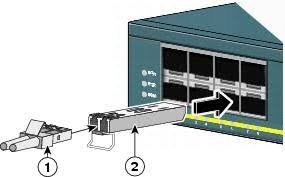
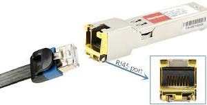
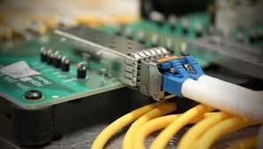
Answer : The small form-factor pluggable (SFP) is a compact, hot-pluggable transceiver used for data communication applications. These small metal devices plug into a special switch slot and support communication over either fiber optic or copper networking cable.
Answer : In fact uplink port can serve as normal port. Therefore, there are no big differences between them. The only difference is that uplink port is connected to higher layer network device to aggregate the bandwidth and must be connected to the normal port on another network device.
Answer :
Copper and fiber cable can be used in SFP module.
Answer :
SFP = 1/2.5 GBPS
SFP+ = 10 GBPS
SFP28 = 25 GBPS
Answer :
QSFP stands for 4 channels of SFP traffic. It stands for Quad (4-channel) Small Form-factor
Pluggable Optics Transceiver. It is a compact, hot-pluggable fiber optical transceiver used for 40
Gigabit Ethernet (40GbE) data communications applications.

Answer :
4 x 1 Gbit/s QSFP = 1GE
4 x 10 Gbit/s QSFP+ = 10GE
4 x 28 Gbit/s QSFP+ (QSFP28) = 100GE
Answer :
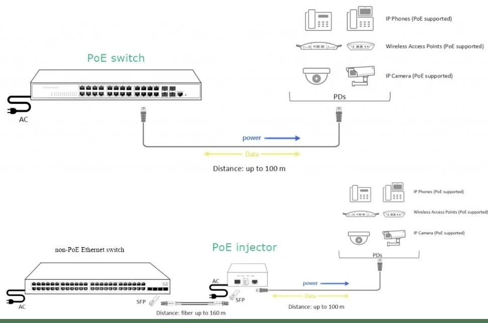
PoE is a revolutionary technology that allows network cable to provide both data and power for the
PoE-enabled devices.
Non-PoE switch, just as the name, is the normal switch, which can only send data to network
devices. There is no PoE in the normal switch to supply electrical power for end users over
Ethernet.
1- General switch issue
- • check power connectivity.
- • check ethernet cable.
- • check switch port and RJ45 connector.
- • Connector should be tight in the port.
- • Power OFF and ON the switch.
2- vlan related issues
To create VLAN
[Huawei] system name Switch A
[Switch A] vlan batch 2 3
To assign interface to specific vlan:
Switch A] interfaceethernet 2/0/1
[Switch A-Ethernet2/0/1] port link-type access
[Switch A-Ethernet2/0/1] port default vlan 2
Switch A-Ethernet2/0/1] quit
3- Spanning-tree issues ?
To avoid loop in network

4- VLAN trunking issues.
If computer is not able to ping gateway
[HUAWEI] interface GigabitEthernet 0/0/13
[HUAWEI-GigabitEthernet 0/0/13]port link-type trunk
[HUAWEI-GigabitEthernet 0/0/13]port trunk allow-pass vlan all
[HUAWEI-GigabitEthernet 0/0/13]quit
